
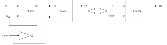
Here two level sensitive D latch works as an edge sensitive D flipflop. The agenda of this post is to understand how the circuit in the left of the diagram works as a D flipflop. We can see a D latch has 2 input pins, Din and Enable. Din is the input and Q1 is the output for the 1st latch. For the 2nd latch Q1 (D) is the input and Q2 is the output.
The enable of the 1st latch is connected to the negative level of the clock. It means, when the 1st latch gets the negative level from the clock it will pass to Q1 what is given in Din. Similarly, The enable of the 2nd latch is connected with the positive level of the clock which means when the 2nd latch gets the positive level from the clock it will pass to Q2 what is captured by Q1 (D). If we see the timing diagram it will become more clear.
Here we can see the output of Q2 (latch 2) is identical of Q (flip-flop). For generating Q2, latch 2 takes input from Q1 (D). Now if we took positive level of clock for latch 1 and negative level for latch 2, what would happen? Think about it.
Simulation Result:


0 Comments